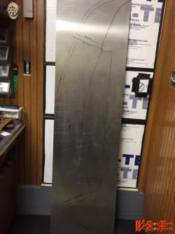
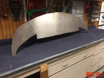
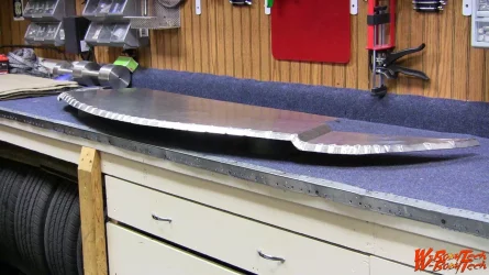
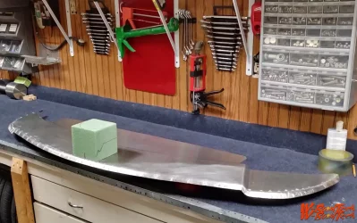
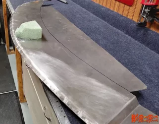
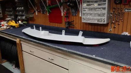
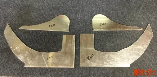
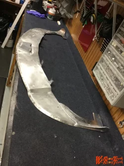
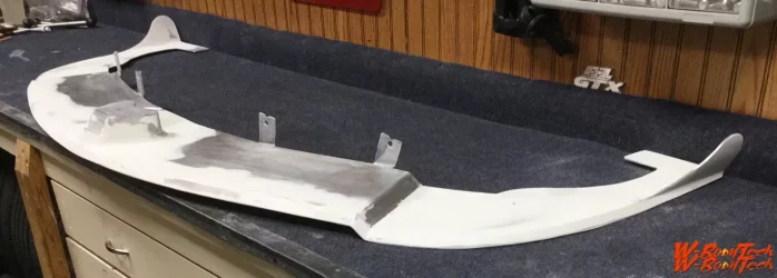
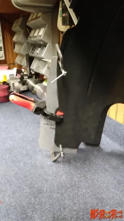
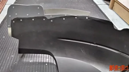
Building a splitter that actually works as a splitter, is an enhancement to the NACA duct Ram air function! Plus enhance the overall front end look! This final design developed over about a 8 month period.
First of all I wanted a splitter that would add to the look of the front end! What does that mean? Well some, or all may not agree with me, but while I love the throwback to the muscle car coke bottle shape of the 7th Gen GP. I have always felt that the front nose, especially from the side view looks weak! Why? Well, my opinion is the front nose from the side comes to a point just above the license plate cover. This is enhanced by stock hood which has a forward slope , than a sharper angle of the cover at the grille area. A short flat area at the license plate cover & than a step back angle below that. This makes a noticeable progressively smaller, top to bottom appearance as you move away from the windshield to the front nose.
I wanted to beef up the look of the front nose, I.E. make the nose look less slopped & more blunt as opposed to pointed. While removing as much as possible the slopped look of the hood towards the nose design.

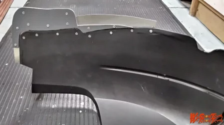
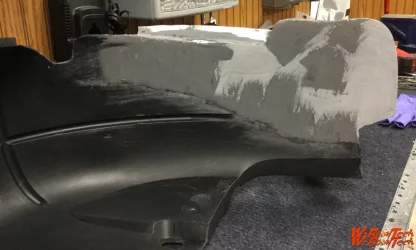
So that first step was the F.1 MPD hood. Because this hood visually tends to raise the front profile of the hood. Than the SD air dam. This piece pushes the lower portion of the front cover out forward, giving the side profile a more blunt look, as well as beefier one. Still I wanted a little more blunt appearance & less roll at the very bottom of the cover. So the splitter needed to be that piece! Plus perform as a splitter & enhance the NACA duct! Notice that the first picture is with the stock front cover & the first splitter I made. The next two are with the add of the SD air dam & the second splitter I made, which was modified to become the final splitter used. Notice in the 4th picture there is an overall appearance of a more blunt front end.

Hopefully these pictures will detail that objective.
That turned out great! I've seen a few splitters on these cars, but nothing as clean as that. It really transforms the front profile. I've been thinking about doing something similar on my '90 and '93 GPs.
 
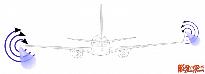
Splitter build. The schematic of the air foil shows the effect the outboard upturned wings have on the air movement over them & why they help supply air to the NACA duct inlet.
 

Attachments

  • 2A15ED3E-7BC4-4E28-AB57-77976F732A34.webp
    2A15ED3E-7BC4-4E28-AB57-77976F732A34.webp
    146.9 KB · Views: 291
  • A7F62DC8-D82F-4800-9E58-51901AFF336C.webp
    A7F62DC8-D82F-4800-9E58-51901AFF336C.webp
    199.5 KB · Views: 265
  • 522B3A81-D003-4BA8-8F11-513B76ECA6CE.webp
    522B3A81-D003-4BA8-8F11-513B76ECA6CE.webp
    251.9 KB · Views: 273
  • EEF8DFFD-5E81-43B0-B281-7C3D753B6816.webp
    EEF8DFFD-5E81-43B0-B281-7C3D753B6816.webp
    194.1 KB · Views: 264
  • E6CB251E-3909-41EF-8ABA-88DB25BA3957.webp
    E6CB251E-3909-41EF-8ABA-88DB25BA3957.webp
    261.6 KB · Views: 299
  • C942BA5A-C049-417C-92C2-FCB5588D9F82.webp
    C942BA5A-C049-417C-92C2-FCB5588D9F82.webp
    105.8 KB · Views: 255
  • DF4BB772-8728-40CF-BAA6-45EFB8ED3E3D.webp
    DF4BB772-8728-40CF-BAA6-45EFB8ED3E3D.webp
    306.6 KB · Views: 255
  • 78AFC9AE-3F0F-4ACB-BB25-58DAE18D6C13.webp
    78AFC9AE-3F0F-4ACB-BB25-58DAE18D6C13.webp
    280.2 KB · Views: 292
  • 5331D8C6-14B6-420D-906A-E61420FAE51B.webp
    5331D8C6-14B6-420D-906A-E61420FAE51B.webp
    143.4 KB · Views: 240
  • FD07A410-5FBE-4DE1-9E39-A0001BA92A9E.webp
    FD07A410-5FBE-4DE1-9E39-A0001BA92A9E.webp
    60.2 KB · Views: 286
Last edited:
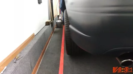
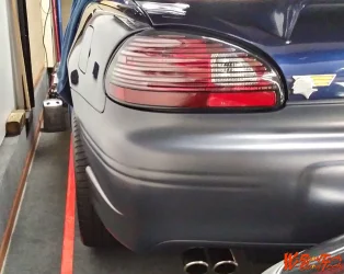
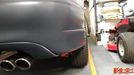
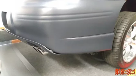
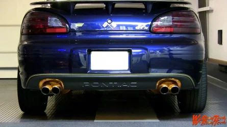
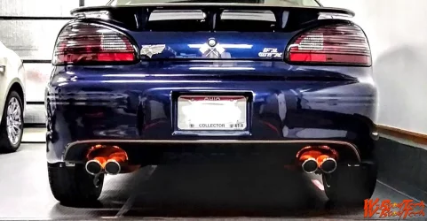
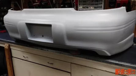
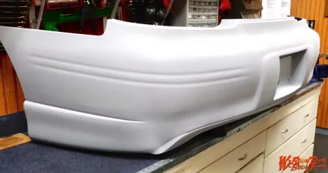
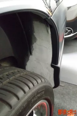
Another body change/upgrade was the widening of the rear cover. As you will see in the suspension post there is a substantial increase in the track width, both front & rear! I have seen other seventh generation GP’s with a wider stance & the thing that has always struck me is how weak it makes the car look from the rear! For me, a car to look intimidating from the rear it needs a wide stance, with wider tires! These wider tires need to be retained within the body though! Not by much, but all of the body! Yet because of the GP’s design, the tires at max width, I.E., just inside the fender wells & even the rocker panels, basically right at the edge. The back cover will sit noticeably inboard of the tires! This, to me makes a weak look; especially from the rear view!

So once again I wanted to change this look! So I needed to modify the rear cover to encapsulate the tires within the body, but just within it. Yet I didn’t want a noticeable shift in the design! Just a subtle one. The results, at least for me was just right.

This change also required a modification to the inner fenders!
 

Attachments

  • ABCEB44C-E7F2-497C-85A3-D53B3E88579D.webp
    ABCEB44C-E7F2-497C-85A3-D53B3E88579D.webp
    62.8 KB · Views: 232
  • 84CE468A-B4C6-4E3A-BB92-74936D5BA892.webp
    84CE468A-B4C6-4E3A-BB92-74936D5BA892.webp
    258.5 KB · Views: 272
  • 8AD0F3CC-63B3-42C7-B10E-EAB8AF0CC5CE.webp
    8AD0F3CC-63B3-42C7-B10E-EAB8AF0CC5CE.webp
    79.3 KB · Views: 279
  • FE8FD50D-7C4E-4F4E-8F1F-C129152ECE42.webp
    FE8FD50D-7C4E-4F4E-8F1F-C129152ECE42.webp
    70.2 KB · Views: 241
  • E2C2EE30-147D-4899-827D-8B95CB5D0C07.webp
    E2C2EE30-147D-4899-827D-8B95CB5D0C07.webp
    158.4 KB · Views: 249
  • EA8F983A-F874-4A44-9377-8268751D4797.webp
    EA8F983A-F874-4A44-9377-8268751D4797.webp
    196 KB · Views: 264
More details on how to proceed with the back cover!
 

Attachments

  • 88A12AC6-6534-4F65-9B46-B5AB91C5A58F.webp
    88A12AC6-6534-4F65-9B46-B5AB91C5A58F.webp
    177.7 KB · Views: 243
  • A119EF75-6248-41BD-AC74-88824C5FEB8F.webp
    A119EF75-6248-41BD-AC74-88824C5FEB8F.webp
    143.4 KB · Views: 276
  • 8641B4DD-50E3-4EA8-99B3-311BB2960ED6.webp
    8641B4DD-50E3-4EA8-99B3-311BB2960ED6.webp
    95.7 KB · Views: 237
  • 925A8793-A412-423E-B869-9A50FB505FA0.webp
    925A8793-A412-423E-B869-9A50FB505FA0.webp
    162.2 KB · Views: 247
  • D4AB4158-4804-4040-96F9-8B67CD0FB055.webp
    D4AB4158-4804-4040-96F9-8B67CD0FB055.webp
    67.4 KB · Views: 264
  • BD7C99A5-F544-4DEA-BA5C-89FA65876C2E.webp
    BD7C99A5-F544-4DEA-BA5C-89FA65876C2E.webp
    93.5 KB · Views: 234
  • 7B7983A0-CCCE-4336-A50A-FF8520750A43.webp
    7B7983A0-CCCE-4336-A50A-FF8520750A43.webp
    215.3 KB · Views: 286
Now that looks a hell of a lot better, Did you use plastic weld/epoxy for this?
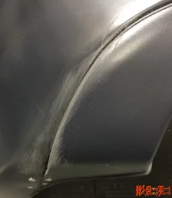
I’ll try to explain this process a little better. Once you split the back cover as I did, following the groove that is molded into the cover, to separate the back valance, per say, from the rest of the cover. You’ll need .025 thick aluminum. Make a plate that can be used to connect the two split pieces of the cover back together using pop rivets, as I show in the one picture. When doing this part you need to have the cover on the car so you can see how much to pull the valance part of the cover back to create the gap I show. This also shows you where the edge of the cover is pushed out to with relationship to the wheel well / tire. I would suggest some clamps will help with this process. Then using more of the .025 aluminum make a insert plate to fill the gap of the cover. This plate should have a folded edge upset to add strength to it. Then I used 3M panel adhesive 38315 to bond that plate to the cover. After that I used only USC icing filler to finish the cover.
All of this said, before you affix any of it permanently you need to modify the inner plastic fenders! These have a huge impact on giving formality & strength to the whole configuration. I will follow up shortly with that information & detail.
 
Last edited:
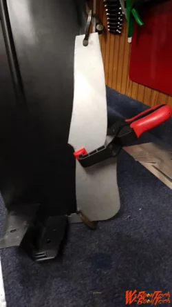
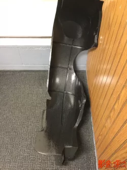
You might want to get a second set of rear inside fender wheel well covers to modify. Either way I would suggest cutting the back cover as above off the car. Then install it completely with the inner fenders in place, but not attached to the cover. Once installed you going to start to pull the fender well part of the cover over to where you want it to fall relative to where you want it on the tire. Once you’ve established its position you’ll need to take some clamps & the aluminum plate, clamp the two separated parts of the cover together. This should make the cover more ridged & create the gap you see between the valance section of the cover & the main cover. Do both sides in this manner to gain uniformity. Now you are going to see a large gap at the wheel well between the cover & the inner fender. You now need a piece of cardboard or construction paper. You will make a template that overlaps on the inner fender & butts up to the inside edge profile of the cover. Just as the original inner well covers originally did. See pictures! The rest of the pictures are fairly self explanatory, but if there are questions please ask.
 

Attachments

  • DFA4ED4F-EE41-4050-B8D9-FC7302E7D7F2.webp
    DFA4ED4F-EE41-4050-B8D9-FC7302E7D7F2.webp
    78.5 KB · Views: 262
  • 63431510-A5C1-444E-AEE0-DF3137DB7E90.webp
    63431510-A5C1-444E-AEE0-DF3137DB7E90.webp
    108.8 KB · Views: 235
  • 8B4C3088-3735-4710-8379-8EB805A81EC4.webp
    8B4C3088-3735-4710-8379-8EB805A81EC4.webp
    96 KB · Views: 237
  • A31002EC-FFDC-4C3E-A074-269729639EE6.webp
    A31002EC-FFDC-4C3E-A074-269729639EE6.webp
    96 KB · Views: 241
  • BDED9CED-5518-4C9A-9DC6-38BF2F4C890A.webp
    BDED9CED-5518-4C9A-9DC6-38BF2F4C890A.webp
    186.5 KB · Views: 247
  • 9E188294-AA8E-40A0-996D-E03FDCDC1521.webp
    9E188294-AA8E-40A0-996D-E03FDCDC1521.webp
    101.6 KB · Views: 248
  • 68C4A698-029D-4938-BEBC-4FD64B1D1D2D.webp
    68C4A698-029D-4938-BEBC-4FD64B1D1D2D.webp
    297.1 KB · Views: 258
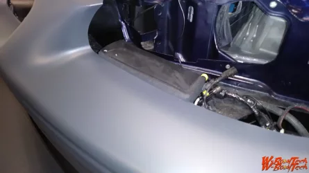
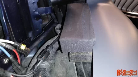
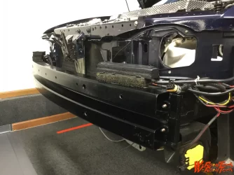
One thing I did not touch on, so I will do it here is this. Both front & rear covers are fairly free floating, I.E. not rigidly mounted! As they, Car manufacturers, love push clips. Which real only keep panels from coming apart, but real does nothing to actually secure parts together or affixed to the actual car body structure. So again for those who have an interest, these are the things I did to change that. The results were front & rear covers that performed more in the manner of the old school cars! Once complete they were solid, I.E. did not move. This included headlights, 5mph impact foam that is mounted to the impact bar among others things.

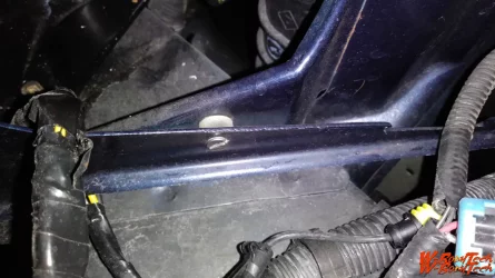
So first up are the headlight brackets. These are actually poorly done. The bracket is fairly long & only attached at each end by spot welds. Leaving a long section of a steel bracket to just vibrate. So I machined nylon spacers to go in between the bracket at about mid point, side to side, both top & bottom. Drilled a hole through the bracket & core support for a 8-32 machine screw. Than opened the hole in the bracket up for clearance. This allowed for a ridged bracket! No more vibration!

Additionally note the affixed pads that are mounted on the impact bar! These are a three stage pad. The first layer is a anti vibration pad & is bonded to the impact bar, than a urethane foam kneeling pad material bonded to the anti vibration pad. Than the top layer is a ¼” neoprene sheet material bonded to that. These all stack up to sit under the headlight housing. When done properly the headlight housings rest slightly on the assembly of pads. The headlights are now fairly ridged! This is extremely important if you are running HID projection lights, as vibration becomes very noticeable when using these lights.

(As A Side Note)

If you are running HID projection headlights you are also running a regular open high beam. Unfortunately this open high beam on its own is pretty in affective. Also unfortunately these cars, unlike their predecessor don’t use all 4 headlights on high, but turn off the projector lights! I changed this! I rewired the high beams so all 4 lights are on when on high beams. This action makes a huge difference on a dark road at night.
 

Attachments

  • 7313998F-75C6-4DBE-B5AE-7AC8EDDFAA2E.webp
    7313998F-75C6-4DBE-B5AE-7AC8EDDFAA2E.webp
    157.3 KB · Views: 235
  • 461122B9-3913-4C85-BE1B-5A5E8F4D564D.webp
    461122B9-3913-4C85-BE1B-5A5E8F4D564D.webp
    73.5 KB · Views: 260
  • F90F7623-CC34-41D8-968F-7F7268EF164F.webp
    F90F7623-CC34-41D8-968F-7F7268EF164F.webp
    150.6 KB · Views: 234
  • 7A0BE067-34CC-4CF6-BEC3-7A1F792ED6D1.webp
    7A0BE067-34CC-4CF6-BEC3-7A1F792ED6D1.webp
    195 KB · Views: 225
  • 59380056-3578-4A60-971F-AA628EF3862B.webp
    59380056-3578-4A60-971F-AA628EF3862B.webp
    168.2 KB · Views: 256
I keep saying this but the attention to detail is top notch on this build, absolutely awesome! always wanted a highly detailed build like this, I forgot to ask, maybe you’ve already said it and I missed it, did you ever get to measure the weight distribution after all the stuff you got to do? It’d be very cool to see the difference!
 
I keep saying this but the attention to detail is top notch on this build, absolutely awesome! always wanted a highly detailed build like this, I forgot to ask, maybe you’ve already said it and I missed it, did you ever get to measure the weight distribution after all the stuff you got to do? It’d be very cool to see the difference!
So to answer your question, yes I did all that upfront work in the very beginning knowing what I wanted to accomplish. I sat down laid out the suspension geometry as it was, then looked at what I could effectively change. Than calculated the numbers & began to make those changes. Now this did take place in incremental steps. In the end the goal was to lower the CG, raise the RC, increase the track width & increase the SSF number. Eliminate torque steer, decrease braking distance, increase power & increase cornering speed as well as stability. The changes were notable in the end.
I needed to look at factory perimeters, (SSF) static stability factor (1.37), weight distribution(65/35), CG(22.45”), front RC(23.70”), rear RC(23.70”) wheel base(110.5), track width ft.(61.7) rr.(61.1) & suspension geometry. These numbers are not very good for a car that you want to handle, they're pretty normal for FWD though.
After modifications, (SSF)(1.76), this is a sports car number, weight distribution (54/46), CG(20.85”), front RC(25.88”), rear RC (25.88”) wheelbase 110.5 (same as OEM), track width ft.(73.5”), rr.(73.25”) & suspension geometry completely modified.
So without getting to technical & lengthy, it goes like this. To effectively increase handling you must lower the CG & raise RC & weight distribution if that applies needs to be 50/50 or as close as possible. So the first thing you would always prefer is to lighten the car where needed, but when you can’t you move the weight around and where necessary you add some, thus was the case here. Than you look to increase the track widths & last modify the suspension components to take advantage of those changes.

I know lots of folks lower their cars & that certainly is their choice, but I don’t believe they really understand what that does to the RC! And while it lowers the weight over the wheels; it virtually has no impact on CG! But! & it’s a big one it, changes the the RC in a bad way!
 
Last edited:
So to answer your question, yes I did all that upfront work in the very beginning knowing what I wanted to accomplish. I sat down laid out the suspension geometry as it was, then looked at what I could effectively change. Than calculated the numbers & began to make those changes. Now this did take place in incremental steps. In the end the goal was to lower the CG, raise the RC, increase the track width & increase the SSF number. Eliminate torque steer, decrease braking distance, increase power & increase cornering speed as well as stability. The changes were notable in the end.
I needed to look at factory perimeters, (SSF) static stability factor (1.37), weight distribution(65/35), CG(22.45”), front RC(23.70”), rear RC(23.70”) wheel base(110.5), track width ft.(61.7) rr.(61.1) & suspension geometry. These numbers are not very good for a car that you want to handle, they're pretty normal for FWD though.
After modifications, (SSF)(1.76), this is a sports car number, weight distribution (54/46), CG(20.85”), front RC(25.88”), rear RC (25.88”) wheelbase 110.5 (same as OEM), track width ft.(73.5”), rr.(73.25”) & suspension geometry completely modified.
So without getting to technical & lengthy, it goes like this. To effectively increase handling you must lower the CG & raise RC & weight distribution if that applies needs to be 50/50 or as close as possible. So the first thing you would always prefer is to lighten the car where needed, but when you can’t you move the weight around and where necessary you add some, thus was the case here. Than you look to increase the track widths & last modify the suspension components to take advantage of those changes.

I know lots of folks lower their cars & that certainly is their choice, but I don’t believe they really understand what that does to the RC! And while it lowers the weight over the wheels; it virtually has no impact on CG! But! & it’s a big one it, changes the the RC in a bad way!
I’m so happy somebody else here knows a lot about the suspension stuff, I’m not as detailed as you with that stuff but I do know quite a bit from growing up at the shop and constantly helping my family with the racing stuff, I have learned a lot over the years and I’ll continue to learn more, the learning will never end. handling has always been my go to thing before speed, I will always love a car that turns better than a car that can only go fast in a straight line, I forgot to mention to you but your part of the reason I started ordering wbody parts agin, decided I’ll do one last full out special (to me) build before I go, unless of course we get these forums big, then I’ll be stuck haha, but I always mention to many people the factory weight distribution on these cars is pretty bad, it’s alright for a fwd car as you mentioned, but for performance driving it’s for sure not good at all and 1000% can be improved, as you have proven. When I did the LFX swap on my 03 Monte I did a lot of things to get weight off the front, ac delete, the engine weighed less, got rid of some other stuff up there that wasn’t necessary, and man, that thing was completely different. this time around I’ll be doing the same thing, but even more in depth, battery relocation, ac delete, etc, by the time it’s done it’s definitely going to stick, that’s for sure. Sorry if this is hard to read, I’m pretty tired Lol. But hey, you talked me back into a w body for now, but after this I’m pretty sure it’s my time to go to better platforms again. ALTHOUGH, this time I’m not going to make the mistake of doing all this to a rusty car, because this time I’m going to keep that build for a very very very long time.
 
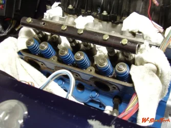
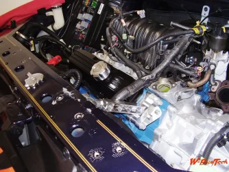
I never finished explaining the build of the Indian. So with that, the 3800 is normally aspirated. That reason was purposeful, as the NA had a better final drive ratio than the SC version. And I knew that there were upgrades I could implement to offset the NA vs SC motor, but the transaxle would take extensive work to change! As you know it’s no small task to pull a transaxle & being a brand new car it wasn’t something I wanted to pursue. So the upgrades on the motor and its peripherals were as follows (heads have been shaved .020, intake ports opened up, ported & polished. Likewise the exhaust valves received the same. 1.9 Yella Terra roller rockers, springs, special grind on the valves & seats. Throttle body machined out to 72mm with a Ultem insulator plate (ultem is a high end, engineered plastic). The PCM was custom flashed by a friend. The stock exhaust on the left bank is not adequate for its duties so a ZZP Power Log replaced it on the left bank & the crossover was replaced with the ZZP SS version, which is slightly larger. The right exhaust manifold is large enough to handle its respective duties. The down pipe was replaced by a Random Technology 3” high flow cat; this cat doubles the CFM output of the stock cat & removes the Ubend. The one piece cat back system was kept, as believe it or not, this setup will work better than any of the aftermarket ones. One reason being that the 3800 motor is quite sensitive to exhaust back pressure. More exhaust noise does not equate to more power! Often the opposite! The most pure power comes from a NA motor! Not a SC or turbo motor!


This is a little hard to explain, but I’ll give it a shot. While a SC & turbo can make more HP in a motor due to compression increase, that increase comes with a negative; heat! Both SC & turbos send super heated air to the cylinder. That heat changes air density, in a less than desirable way. Don’t get me wrong, power is power! Remember I’m speaking of exhaust, its function & it’s sound! Pure power is hard to muffle! My Z/28 302 at almost 600 hp was a NA motor. Ran headers & a stock exhaust system. It wasn’t loud standing next to it, but it wasn’t quiet! It rumbled with deep vibration. That pure power while not loud could be heard more than an ⅛ of a mile away! How do I know that? My wife would tell me lots of times! “I knew you were coming, I could hear the rumble”. Just at a 700 rpm idle you could hear that car more than 100’ away! Not load just this low deep rumble. The Indian has that just a bit. Not loud, just a bit of a rumble, but nowhere even comparable to the Z! Yet when you put your foot into it that rumble turns to the reminiscent sound of a throaty V8. The SC & turbo motors I’ve heard have a much higher pitch sound! That is due to air density!
 

Attachments

  • 3.8 clean.webp
    3.8 clean.webp
    79.2 KB · Views: 2
  • P2100403-1.webp
    P2100403-1.webp
    214.1 KB · Views: 1
  • PA050373.webp
    PA050373.webp
    359.2 KB · Views: 1
  • undercarriage.webp
    undercarriage.webp
    187.1 KB · Views: 1
  • front subframe sec.webp
    front subframe sec.webp
    161.8 KB · Views: 1
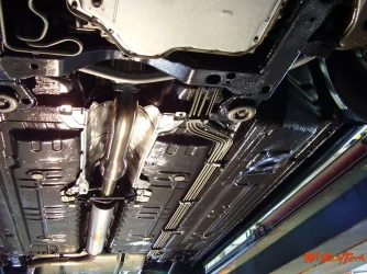
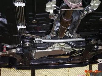
When it came to the suspension I needed to look at the factory perimeters, (SSF) static stability factor (1.4), weight distribution(65/35), CG(24”), RC(15.7”), wheel base(110.5), track width ft.(61.7) rr.(61.1) for some of the suspension geometry. These numbers are not very good for a car that you want to handle, they're pretty normal for FWD though.

After modifications, (SSF)(1.68), weight distribution (54/46), CG(19.2”), RC 20.4”), wheelbase(same), track width ft.(64”), rr.(63.7”) for comparison of suspension geometry above after modifications.

So without getting too technical & lengthy, it goes like this. To effectively increase handling you must lower the CG & raise the RC & get the weight distribution as close to 50/50 as possible. The first choice most people make is to lower CG by using lowering springs/struts. That should not be the first choice! When you lower the CG by lowering the sprung suspension, AKA car body over the unsprung suspension it actually has a negative impact on handling. Most may doubt this, but it is fact! Vehicles that are lowered via lowering springs/struts feel more stable in a corner because you have changed the CG in a positive manner, but, & it is a big negative! When you change the CG in this manner you also negatively change the RC, AKA lower it! And that is bad! In some cases, a hard corner at higher speed can cause the car to lose control! In the worst case scenario it can flip! This is called the jacking force.
 
I will preface this part of the build with a huge thank you to Caroll Shelby! Who at my tender age of 15 inspired me about braking! Enzo Ferrari said he could go from 0 to 100 in 10 seconds! Carrol Shelby said he could go from 0 to 100 & back to 0 in 13.8 seconds! He was wrong! He did it in 11.5 seconds! This record stood for a half century!

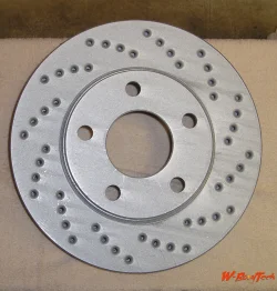
For the Indian the brakes are a bit of a different animal as opposed to what most folks believe! So new OEM lines were used and most nearly all the rest was either cleaned up and reused, made or modified. All the hardware might appear as OEM, to the casual observer, but that’s where it stops. Rotors, pads, fluid, O’rings, peddle ratios & material selections are all changed, I.E. non stock or custom. From a purely pragmatic standpoint a car brake system is a fairly simple hydraulic system. It's applied physics, the total weight, weight distribution, center of gravity, roll center and weight transfer, along with coefficient of friction for materials & a lot of math! Then add fluid chemistry for work function. This may sound complicated, but it's not. Yet the OEMs have complicated the hell out of it to C.T.A…. So I take my systems back to the basics that work best and longest without problems. OEMs use large square and I use the word loosely, O’rings, why? O’rings are literally a mechanical device, there is a whole mathematical science around them, they are not a gasket. They are round for a purpose and the tiny center ridge that runs around them is not a parting line. I could detail more, but that's not the point here. So number one I change the O’rings to an actual O’ring and from buna rubber to Viton. Most brake systems hold residual pressure which in turn creates brake drag. In every system I run I look for a way to negate or elevate that pressure.

So the brakes were modified, both calipers & rotors & the brake fluid was changed originally to Valvoline Syn Power DOT5 fluid & now Bosch ESI 6 The specs on both of these fluids is an entire category above OEM fluid! Unfortunately Valvoline Syn Power was discontinued. Then there is all the custom made hardware & gingerbread which is too much to name. In the end this ABS braking system went from a system that needed ABS to a system that will out stop nearly any OEM brake system that has ABS today! And no matter how aggressively you hit the brakes, the car just flat stops! No ABS ever triggers; because the coefficient of friction is that good! The Indian, like my “69” Z which had my entire hand made brake system on it, stopped around 75 feet shorter of a known stop light! I use this light to measure stopping distance! All of this while still using the original factory calipers! No bigger calipers! No bigger rotors! But different materials! You see, just changing a few key things, like O’rings, brake pad composition, rotor metallurgy, pedal ratios has a dramatic impact on the physics of braking!
 

Attachments

  • IMG_0680.webp
    IMG_0680.webp
    351.3 KB · Views: 1
  • IMG_0679.webp
    IMG_0679.webp
    291.1 KB · Views: 1
  • P1010144.webp
    P1010144.webp
    309.6 KB · Views: 0
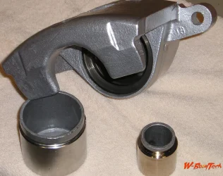
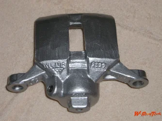
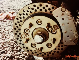
Just for those that might have an interest these are two pictures of the brake system I designed & built for my “69” Z. Way back in 1980. I used to have more pictures, but I don’t know where there are as I seldom reference them anymore. These were three piston calipers set in double shear. The braking performance of this system was incredible! These are the rear brakes. The rotors were made as well. This system stood untouched for 24 years & over 80,000 miles when it was sold in 2004. I don’t know how many more miles or years they went, obviously. But in 2004 there was still more than half the pads material left & virtually no wear on the rotors. That is how good brakes can be if you truly match materials!
 

Attachments

  • FullSizeRender 14.webp
    FullSizeRender 14.webp
    271 KB · Views: 1
  • FullSizeRender 13.webp
    FullSizeRender 13.webp
    239.9 KB · Views: 1
Similar content Most view View more
Back
Top