Welcome!

By registering with us, you'll be able to discuss, share and private message with other members of our community.

SignUp Now!
So without getting to technical & lengthy, it goes like this. To effectively increase handling you must lower the CG, the RC & the weight distribution if that applies, and it did here. So the first thing you would always prefer is to lighten the car where needed, but when you can’t you move the weight around and where necessary you add some, thus was the case here. Than you look to increase the track widths & last modify the suspension components to take advantage of those changes.

235 lbs. was added to the Indian and all but 15lbs. of it was at or below wheel centerline. The equivalent of 90lbs was removed from the front nose area and relocated to the rear of the car, again below original CG. 40 lbs was added to the rear impact bar. Part of the weight redistribution was the relocation of the battery to the trunk spare tire well. Additionally the entire frame structure and dead spaces (lower firewall & rear cavity structure) were filled with structural urethane foam, contributing 22 lbs of the 235. The rear suspension carrier was reenforced to reduce flex in hard cornering, extra large lateral bars & trailing arms were installed. Redesigned upper rear strut mounts. Redesigned front lower A-arms to reduce torque steer and increase power transfer to the ground. Front struts components redesigned for increased corner stability & power transfer through better spring function. Heavy duty police package springs front & rear were installed. Upper strut bearings replaced with industrial grade pieces, better responsiveness and smoother wheel control & stability. Both front and rear sway bars were replaced with solid ZZP pieces! Their end links were replaced with my design. The front bar was replaced with a solid 34mm bar with larger diameter, shorter and stiffer end links. While the rear bar was replaced with a solid 25 mm diameter bar and a redesigned set of end links as well. Both sets of end links make a significant improvement over the OEM units as they make the bars do what they were designed to do, prevent body roll and keep the wheels planted on the ground.
Aw man, seeing all of this stuff makes me really want to build one of these cars again, I just don’t know if I could justify putting so much money into such an old platform, many other routes that I could go and have better results but I’ll forever have wanting to build another one of these cars stuck in the back of my head 🤣
 
Very very cool steering wheel! that is a very cool mod man! never seen anybody do that much effort, usually people just toss a cheap aftermarket one on haha
I started making these back in the late “70s”. First one was a 12” for my Z/28. Made one a few years back for a friends GTO.
 

Attachments

  • 19986182-B651-414A-A959-C4D6F69E8118.webp
    19986182-B651-414A-A959-C4D6F69E8118.webp
    23.2 KB · Views: 87
  • ABFA009D-47C3-4C8E-930B-2485A4EA87EB.webp
    ABFA009D-47C3-4C8E-930B-2485A4EA87EB.webp
    300.6 KB · Views: 80
  • 412D3B29-38F6-4827-93DB-B1A813287F2D.webp
    412D3B29-38F6-4827-93DB-B1A813287F2D.webp
    127.2 KB · Views: 89
  • FA648931-8FD1-4D21-80F4-9B9DD88D29D4.webp
    FA648931-8FD1-4D21-80F4-9B9DD88D29D4.webp
    345.9 KB · Views: 91
  • 27779680-CDC4-431B-9626-1ECC982B2786.webp
    27779680-CDC4-431B-9626-1ECC982B2786.webp
    162.5 KB · Views: 90
  • E48B6F5C-8604-4119-93D0-E3BBDBB9272C.webp
    E48B6F5C-8604-4119-93D0-E3BBDBB9272C.webp
    182.7 KB · Views: 76
  • C2321D13-0A54-41CF-A09F-8EB72BFD652D.webp
    C2321D13-0A54-41CF-A09F-8EB72BFD652D.webp
    271.2 KB · Views: 80
  • 3E5A8556-40B5-48C1-8B32-02F2A30364CE.webp
    3E5A8556-40B5-48C1-8B32-02F2A30364CE.webp
    238.8 KB · Views: 83
  • 5E36B780-7BD8-4FAC-A347-37B7E75FFB9E.webp
    5E36B780-7BD8-4FAC-A347-37B7E75FFB9E.webp
    220.4 KB · Views: 80
Aw man, seeing all of this stuff makes me really want to build one of these cars again, I just don’t know if I could justify putting so much money into such an old platform, many other routes that I could go and have better results but I’ll forever have wanting to build another one of these cars stuck in the back of my head 🤣
I can’t say I disagree, because I understand what you mean. Yet for me, what has always driven me is what I see that could be! The big thing Detroit usually missed! I’ll explain.
Most car designs look old by the time they’re 15 years old, maybe sooner. Meaning you look at a car & think, wow I use to think that looked good! What was I thinking! There are literally only a limited number of car designs that look as good today as they did when they debuted! The rest fall into one of three other categories; modified, just nostalgic or who cares!
Examples: the 1969 Camaro is the icon of the first generation F body, but even though I owned that car the basic model in original trim doesn’t look all that impressive now! So put it in the nostalgic column. Now add the Z/28 package to it & maybe even the RS option & that all changes. The same applies to the first Mustangs, but add a fastback & the looks change completely. These are examples of nostalgic vs modified, even though the body mods, & sometimes even drivetrain & suspension were factory. Which explains why today about 90% of every “69” Camaro you see has a cowl hood, strips & bigger rims & tires!
Now the plain Jane GP, no spoiler, no leather, no extra anything is pretty bland today, IMO. Look at the current Charger! No matter how subtle the body changes are once you get to the scat back option on up it’s day & night in the intimidation factor just by looks!

So that’s how I see the seventh generation GP! It has all the makings of a great platform & even a greater exterior presence. Maybe even in time, a true classic. It just needs a big push! And then there’ll be the ahh factor that not just makes it, but makes it unique!
 
The first goal for the front & rear sway bars were to redesigned both sets of end links. This made good improvements in the OEM sway bars performance, but it was still way to inadequate. So I replaced the rear bar first with a hollow 22 mm, it just wasn’t enough to give the total flat corners I was looking for. So next came ZZP solid 25 mm diameter bar! That coupled with the 34 mm front bar & both sets of redesigned end links made a significantly marked improvement over the OEM units as they are bigger sway bars & end links, now the end links make the bars do what they were designed to do, prevent body roll and keep the wheels planted on the ground.

Additionally BMR lateral bars as well as their traction bars were installed. These are a substantial improvement over the factory bars. Comparatively speaking they are huge! When you look at the O.D. of these bars & their inside diameter they are nearly 8 times stronger! When I purchased the lateral bars I bought 4 adjustable bars. In this way you have a infinite ability to adjust rear wheel toe as well as finely adjusting camber! Which for me was important due to the large increase in the track width. Likewise, similar to the front struts I made a modification to the upper part of how the strut interfaces with the body attaching point.

This mod places a 85 durometer urethane spacer between the strut mounting plate & the car body! Why? The upper rear strut mount is a thin rubber coated steel plate. It does not actually fit flat it tends to warp slightly & flexes under heavier lateral side loads.This urethane spacer is ½ “ thick fairly stiff, if you know what 85 durometer is like, some might even say hard, but has some ability to give. This spacer is bolted to the mounting plate & than longer studs are used to go through the spacer & mounts to the body in the normal manner.

Additionally each knuckle was blueprinted. What does that mean? These are cast pieces, not extrusions. Which means they are weaker than if they were extrusions. So every casting line, every sharp ridge, every part of the casting that could become a fracture point was either removed, filed smooth or radiused to prevent fractures. Likewise the center bore for the bearing was resized with a sleeve to give a snug fit for the bearing.
 

Attachments

  • 31756D5E-4297-4559-9D1D-C6E5A8889497.webp
    31756D5E-4297-4559-9D1D-C6E5A8889497.webp
    63.5 KB · Views: 82
  • 719F2A48-13D3-46A5-A289-8982D4E9DE25.webp
    719F2A48-13D3-46A5-A289-8982D4E9DE25.webp
    188.9 KB · Views: 79
  • 4ACE528C-856A-4B56-B58E-D7917B08B9B7.webp
    4ACE528C-856A-4B56-B58E-D7917B08B9B7.webp
    207.1 KB · Views: 96
  • 244A1B42-0D6C-48C0-9C07-26D3824F42DD.webp
    244A1B42-0D6C-48C0-9C07-26D3824F42DD.webp
    53 KB · Views: 87
  • E260293B-BC16-4961-92D3-4CEF09C8487C.webp
    E260293B-BC16-4961-92D3-4CEF09C8487C.webp
    244.8 KB · Views: 90
Speaking of the suspension, I would offer this cautionary story if you plan to build a ground pounder as they are called! I can not speak about all FWD’s as I have not built the suspensions of all manufacturers, but of all GM & the like there is a serious issue with McPherson strut/knuckle suspension vehicles, especially when it comes to building an aggressive handling suspension. This is due to the illogical application of the wheel bearing design!

In a traditional rear wheel drive the bearings are installed on a traditional spindle with two tapered roller bearings. This design can not fail, I.E. the wheel falls off! Other than to have a bearing go bad, there is little else to occur beyond stranded! As it would be virtually impossible, due to bearing failure, for the wheel to come off!

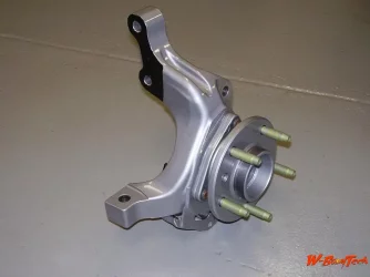
That is not the case with a FWD! The rear hub bearings are held in place by bolts that thread into the knuckle. Which pushes the wheel hub into the knuckle. The wheel obviously bolts to the hub. If the hub bolts that are threaded into the knuckle fail for any reason, the hub has nothing to keep it in the knuckle, or the wheel on the car!

This was such the case for me! Fortunately I caught my problem before it became a dilemma or catastrophe. When I built this suspension many years ago I built everything new from the ground up, including hub bearings. They were done more than correctly! The fit to the knuckle was a little tighter than factory & the torque was 5 pounds more. And yes it has taken nearly 20 years to raise its head, but that’s only about 15,000 miles.

So it went like this. For the last half of last summer & most of this past summer every time I would make a hard, I.E. aggressive right turn I would get this rattling noise from the left rear that kind of sounded like decelerating exhaust while in the cornering sequence. Straight forward driving it seemed quiet. Over & over again I would check & recheck, exhaust, brakes, tire rub, suspension clearance, suspension component torque, etc., but nothing! It drove me nuts, because I knew something was wrong. I took out the back seat pulled the access plate to the fuel pump. Now it appeared more metallic then. Took it on the freeway & now I would hear a intermittent hard metallic crack. That was it, I knew I needed to put it up in the air & go through the whole back suspension piece by piece, oh great!

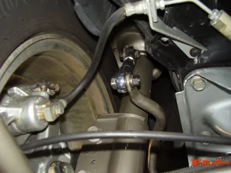
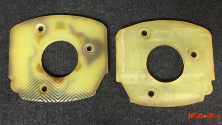
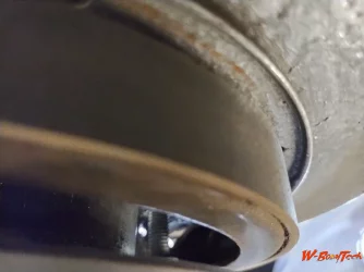
Well I didn’t have to go far. Removed left wheel, caliper, rotor & bingo! There it was! Looking through the access holes of the bearing hub tire mounting flange was a hub mounting bolt. Loose & bent. I replaced it & checked the torque on the other 3 bolts. All were loose! I check the other side. One needed re-torque slightly, the rest were good.

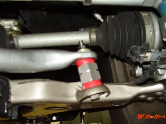
My take on this is this. The hub bearing mounting setup is poor at best, but the front is better than the back. The front use 3 larger bolts mounted from the back. This is better because in hard cornering, the loaded wheel, this places the bolts in compression & the bearing receives more of a angular vertical load. So while this is far less than optimal, it’s by far better than the back.

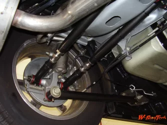
On the other hand the back is abysmal! In a hard corner the rear load wheel has a similar load as the front, but the bolts are a third of the diameter & they’re being stretched & the following wheel is also being stretched because they hold the bearing hub from the front.

I have a new design for these that I will build this winter. As I do I will share it with you folks so if you chose you’ll be able to incorporate it as well. This design will be more in the vain the a spindle type attachment that will have a means to be a fail safe design that would prevent this type of bolt failure.
 

Attachments

  • 382DA398-4BA9-4475-967D-5EB266912A53.webp
    382DA398-4BA9-4475-967D-5EB266912A53.webp
    155.2 KB · Views: 61
Thanks for posting this, over the years at the shop I’ve never seen one come loose but glad to know it’s a possibility!
 
Yes, that post was to make anyone who wished to do any of the modifications I’ve done aware of the possibility. I wouldn’t think you would see this type of issue in a non modified vehicle. I have no doubt that the aggressive nature of the Indian’s suspension is the reason for the occurrence. When you’ve increased the track width by a foot, stiffened the suspension components so they transfer power effectively to the ground were it belongs & you actually use it in the manner you built it for; it’s not surprising!
What is surprising is that any head engineer would let such a flawed design make it to production! Let alone prevail for decades & hundreds of thousands of vehicles. The simplest of design change would have kept the possibly of the catastrophic failure like the wheel coming off, should have been the mind set no matter how unlikely.
Thanks for posting this, over the years at the shop I’ve never seen one come loose but glad to know it’s a possibility!

As I step through this design change modification I’ll post its progression.
 
Back
Top